- The speed of the white steel knife should not be too fast.
- For coppersmiths, use white steel knives less frequently, and more use flying knives or alloy knives.
- When the workpiece is too high, you should use different length cutters to roughen it in layers.
- After roughing with a big knife, use a small knife to remove the remaining material to ensure that the remaining amount is consistent.
- Flat-bottomed knives are used to process planes, and ball knives are used less to reduce machining time.
- When the copper worker cleans the corner, first check the size of the R on the corner, and then determine the size of the ball knife to use.
- The four corners of the calibration plane should be flat.
- Where the inclination is an integer, use an inclination knife to process, such as pipe position.
- Before doing each process, think about the margin left after the previous process is processed, so as to avoid empty tools or excessive machining.
- Try to take simple toolpaths, such as shape, grooving, one-sided, and avoid the surrounding height.
- When walking WCUT, if you can go FINISH, don’t go ROUGH.
- When the shape of the light knife is rough, polish it first, then polish it. When the workpiece is too high, polish the edge first, then polish the bottom.
- Set tolerances reasonably to balance machining accuracy and computer calculation time. When roughing, the tolerance is set to 1/5 of the margin, and for light knife, the tolerance is set to 0.01.
- Do more procedures to reduce the time of empty knife. Do a little more thinking to reduce the chance of error. Do a little more auxiliary line auxiliary surface to improve the machining condition.
- Establish a sense of responsibility and carefully check each parameter to avoid rework.
- Diligent in learning, good at thinking, and continuous improvement. For non-planar milling, use more ball cutters, less end cutters, and don’t be afraid of receiving the cutter; small cutters clean the corners and large cutters for finishing; don’t be afraid to make up the surface. Properly making up the surface can increase the machining speed and beautify the machining effect.
- High hardness of the blank material: better up-down milling. Low hardness of the blank material: better down-milling. The machine tool has good precision and rigidity. Finishing: more suitable for down milling, on the contrary, it is more suitable for up-milling parts. It is strongly recommended to use it. Down milling. Rough machining: up-milling is better, finishing: down milling is better. Tool material has good toughness and low hardness: more suitable for rough machining (large cutting amount machining). Tool material has poor toughness and high hardness: more suitable for finishing (small cutting amount machining) ).
- Copper machining method and precautions: before writing the tool path, after finishing the three-dimensional picture, move the center of the graphic to the origin of the coordinate, and move the highest point to Z=0, then it can be processed, and the copper spark can be processed negatively. Reserve amount. Before machining, check whether the clamping direction of the workpiece is the same as the direction of the graphics in the computer, whether the alignment in the mold is correct, whether the fixture is blocking the machining, and whether the directions of the front and rear molds match. Also check whether the tools you use are complete, the benchmarks in the calibration table and so on. Matters needing attention when machining copper: For determining the spark level, the general reserved amount for young males (that is, fine males) is 0.05~0.15, and coarse males are 0.2~0.5. The specific spark level can be determined by the master of the mold. Are there any dead corners that cannot be processed by the copper public? Do you need to dismantle one more scattered public? The tool path for machining copper is generally: large knife (flat knife) to open rough-small knife (flat knife) to clear the corner, and smooth knife to use a ball knife to smooth the surface. Generally, teachers use a flat knife instead of a ball knife. After the big knife, use a small knife to make the roughness, and then use a large ball knife to smooth the surface, and then use a small ball knife to smooth the surface. Using a knife to process the dead corners that the big knife can’t pass can limit the range of the knife, so as not to broadcast too many empty knives. Copper males, especially young males, have relatively high accuracy requirements. The tolerance is generally 0.005~0.02, and the step distance is 0.05~0.3. When the copper is exposed to the thickness, leave the over-cut position of the ball tool position, that is, make the copper male profile thick and deep by one knife radius. Tonggong also needs to process the median and calibrate the benchmarks, and calibrate the coppers during spark discharge. Generally, the coppers processed by the three sides (up, down, left, and right) must have three reference planes. Copper is a material that is relatively easy to process. The cutting speed and rotation speed can be faster. When roughing, the machining allowance is 0.2~0.5, depending on the size of the workpiece. The machining allowance is large, and the knife can be moved faster when roughing. ,Improve efficiency. Note: The parameters in the brackets are the parameters when the high-speed steel knife is roughing the steel. The above cutting speed refers to the roughing, the required shape F=300~500, and the steel smooth knife F is 50~200.
- The problem of the thick front mold: first, rotate the copper map 180o in the front view or the side view to become the front mold picture, of course, add the pillow position and the PL surface; the original body needs the place where the front mold should be left. , Don’t use the mirror body method to change the copper drawing to the front mold drawing, sometimes it will be wrong (when the copper drawing is asymmetric in the X and Y directions). There are two difficulties in the machining of the front mold: the material is relatively hard; the front mold cannot be easily welded and cannot be mistaken. The principle of using a knife when the front mold is rough is similar to that of the copper worker. The big knife is used to open the thick knife. The thick knife is light knife and the light knife is light knife. However, the front mold should use a big knife as much as possible. Do not use a knife that is too small. ) Use round nose knives as much as possible when opening rough and smooth knives, because this kind of knife is big enough, powerful, and when machining front molds with parting surfaces, there is usually a problem. Quasi-loud number, and 0.2~0.5 machining allowance should be left in the cavity (leave it out for sparks). This is to correct the surface of the mold cavity by 0.2~0.5 in the positive direction, and set the machining allowance to 0 when writing the tool path. The cutting range is usually limited when the front mold is roughed or smoothed. Remember that the range you set is the range of the tool center, not the range of the tool boundary, not the range that the tool can process, but a larger tool radius. The commonly used tool path method for front mold roughing is curved surface grooving and parallel light knife. When the front mold is processed, the parting surface and the pillow surface are generally processed to the correct number, while the collision surface can be left with a margin of 0.1 to prepare the mold.
- Problems often encountered after machining the mold: the rear mold has two types: the original mold or the inlay mold. The rear mold is made of steel like the front mold, and the material is harder. It should be processed with a knife as much as possible. The common tool path is curved surface grooving. The shape, parallel milling cutter, the principle of selecting the cutter is to open a large knife and a small knife to open a thick knife, a light knife, a small knife, and a light knife. The post-mold picture is usually made by reducing the material level of the copper drawing and adding the PL surface, pillow position, and the original body. If the material level is relatively uniform, you can directly leave the negative material level in the machining information, but PL (Parting surface), the pillow position and the contact surface cannot shrink the material position. At this time, you can first correct these faces by a material level or draw the subject. A problem often encountered by the original division is that the ball knife cannot clear the sharp corners. At this time, you can use a flat knife to go to the steep slope of the curved surface to process the clear corners. For example, the back mold is divided into a hidden frame and a core. Please pay attention to the empty knife several times, otherwise the frame will have a slope, the upper edge is accurate, the lower edge is small, it is difficult to match the mold, especially the deeper frame, we must pay attention to this problem, and the knife of the light frame should be new. Okay, and choose a larger knife. If the core is too high, you can turn it over and process the frame first, and then assemble it into the frame, and then process the shape. Sometimes there is a branch. Be careful not to overcut the shape with a ball knife. Be sure to protect the support step. In order to facilitate the matching mode, the frame size can be smaller than the outer dimension of Koxin-0.02/s. The tolerance and step distance of Koxin light knife can be slightly larger, and the tolerance is 0.01~0.03, and the feed is 0.2~0.5.
- Problems in bulk copper machining: sometimes the overall copper machining is difficult, there are dead corners that cannot be processed, or it is not easy to process, and the required tool is too long or too small, you can consider adding one more copper, sometimes Partially need to clear the angle of the copper, the machining of this kind of copper is not difficult, but we must figure out the deviation of the good spark, calibration benchmarks.
- Machining of thin-disc copper male: This kind of copper male is easy to change during machining. When machining, use a new knife, the knife should be small, and the knife should not be too large. The length a can be adjusted first during machining. But leave a large margin for d (such as 1.0mm) and then walk on both sides. Each time the depth is h=0.2~1. Do not go too much in depth, and don’t go around the knife in a circle, but divide it into two sides and walk separately.
- The direction of left and right parts and one out of two parts: Sometimes a set of molds will produce two parts. For the left and right parts, the graphics can be made by mirroring. If there are two identical parts, the graphics must be flat or rotated in XY, and they must not be mirrored. Be careful not to reverse the direction.
- The direction of the mold: The four guide bolt holes of the mold blank are not completely symmetrical, one is asymmetrical, so when machining the front and rear molds, please make sure that there are benchmarks on each template, and the processed front and back molds are closed. It must be benchmarked against benchmarks, especially for the mold forming the original mold blank. Pay attention to the direction when drawing the picture. The direction of the Tong Gong is the same as that of the front view (top view), the direction of the core and the Zangke frame are the same as that of the Tong Gong, and the front mold is the opposite. Some decorative lines such as grooves or bosses on the curved surface are not easy to process because they are relatively narrow. For the groove, we generally avoid the groove, that is, mill it deeper, and then add a loose male to make a countersunk surface. Generally, the boss can only be made a loose male separately, and a large copper male does not, so as to ensure the quality.
- Mold and product fit tolerance: A set of products usually has several or more than a dozen parts. The main fit dimensions of these parts are guaranteed by CNC machining center. It is very important to choose a reasonable tolerance, especially for some product designs. The figure does not consider coordination issues. The matching of the bottom and the surface shell is undoubtedly a 0 to 0 fit, and the positioning is guaranteed by the branch. The tolerance of the concave branch and the convex branch is generally 0.1mm, unilateral. Accessories on the big body, such as transparent mirrors, generally have a smaller shape than the size of the big body by 0.1~0.2 on one side. For movable accessories on the big body, such as buttons, the shape of the accessories is 0.1~0.5 smaller than that on the big body. The surface shape of the accessories on the body should generally be the same as the surface shape of the body, which can be removed from the surface of the body.
- Mold inclination (draft angle): The mold inclination must be made for the plastic mold, otherwise it will be scratched. If the drawing is not marked, you can discuss with the mold master. The mold inclination is generally 0.5~3 degrees. For etched molds, the draft angle should be larger, 2~5 degrees, depending on the thickness of the etched pattern.
- Tooling problem: In many cases, when the cutting tool is just milled, the amount of tool eaten is relatively large, which is likely to cause the tool to break or spring the knife. At this time, you can first open the lower tool position or lift the knife to go, or the day Cut the knife outside the material, in short, we must fully consider this issue. Knife grabbing, flicking, and dropping When the machining volume is relatively large, the tool holder is too long, and the tool is too small. This often happens. The machining volume is relatively large, especially when the concentration of cutting is high, it is easy to happen. For example, the light side depth H=50mm diameter 3/4 cutting, we can divide the 25mm secondary machining, and it is not easy to happen. The tool clamp is too long. The length of the tool is very important for machining. It should be as short as possible. It is easy for beginners to ignore this problem. The clamping length of the tool must be marked on the program paper. It is easy to grab a knife when turning a corner. The solution is to clear the corner layer by layer with a smaller knife, and then change the side of a larger knife. Like the semi-circular groove with diameter 8 as shown in the figure, it is easy to grab the tool if it is directly processed with the R4 knife. The solution is (1) use R3 to scan the tool path (2) first use R3 to make rough, and finally Use the R4 knife to clean the corner light knife.
- Grinding knives: CNC machining centers often need to sharpen various knives for different shapes. Various shaped knives are worn out and need to be sharpened. Only the following accounts can be used to grind a usable knife1. The four corners of the tool should be the same height2. Point A is 3 tools higher than point D. The forward (face) is higher than the back, that is, there is a certain clearance angle.
- Overcut check: Overcut is a problem that often occurs in masterCAM, so be careful. Over-cutting may occur in multi-curved surface roughening, light knife, tool path trimming, shape, grooving, even if the parameter settings of the chest and the three-dimensional diagram are correct, it may happen. Some of the errors are the software itself. The main inspection method is Simulate the tool path again and check repeatedly in the top view and the side view. The tool path that has not been checked is not allowed to be used on the machine. During contour milling, improper selection of the position of the lower tool will result in over-cutting, which can be avoided by changing the position of the lower tool.
- Milling direction: CNC machining centers are generally down milling, unlike the up-cut milling of milling machines. The reason is that CNC machining centers have better rigidity and are not easy to let the tool. The backlash is small, and the milling shape or inner groove is left-compensated. When machining a symmetrical shape, the tool path of the contour cannot be mirrored, otherwise the machining effect of the mirrored side will not be good. The writing method of the program paper In order to communicate with the personnel operating the machine tool, the program paper should include 1) program name 2 tool size and length 3 machining tool path method 4 machining allowance 5 rough or light knife 6 drawing file name 18. Graphic management computer drawing application For proper file management, it is best to create a catalog for each product, and give a different name to each part. For example, the name of the copper drawing is A10, the rear drawing can be A10C, the front drawing is A10CAV, and the scattered copper drawing is A10S1. , So it’s clearer. 19. Format conversion between different software: Communicate with AutoCAD, DWG files can be read directly for MastCAM 7 and above, and DXF format can be converted into DXF in autocad for versions lower than 7. Other CAM software such as (cimtron, pro/e, UG) can be converted to IGS format first.
- DNC usage: After the program is completed, after checking, it can be copied to the DNC computer for actual machining without any problems. There are two methods for copying the program: 1 copying with a disk, 2 sending it through the LAN. Then start the DNC software, find the program you want to run, and press ENTER.
- Coordinate system: There are three types, mechanical coordinate system, machining coordinate system, and temporary coordinate system. In the mechanical coordinate system, the mechanical zero point is a reference point on the machine. After each power-on, the origin is determined after returning to zero. The position of the mechanical zero point is determined by the machine factory and should not be changed. The machining coordinate system is used for workpiece machining. It is a sub-coordinate system of the mechanical coordinate system. A point in the mechanical coordinate system (usually the center point of the workpiece) is taken as the coordinate origin, and the mechanical coordinate value of this point is recorded as the machining The origin of the coordinate series can be set as the machining coordinate system. Temporary coordinate system: reset each point as the coordinate origin at any time. Corresponding to the coordinate value, there are also three kinds of coordinate values: mechanical coordinate value, machining coordinate value, temporary coordinate value (also called relative coordinate value) 22. Commonly used filter value: commonly used filter value 0.001~0.02, filter radius R=0.1~0.5. Use a large value for the rough toolpath, a small value for a smooth surface toolpath, a large value for a smaller surface radius, and a smaller value for a larger surface radius. Filtering can effectively reduce the program capacity and make the tool pass more smoothly, but if it is too large, it will affect the machining accuracy.
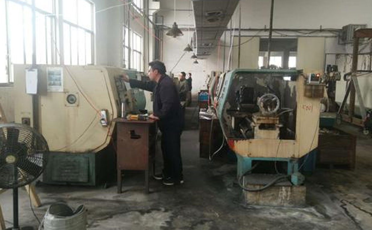
The Essence Collection Of CNC Machining Programming Experience
Cnc Operating